This discussion of optical communications is very basic. I am sure that many experimenters are well beyond this point, but there are always those who are just getting into this interesting subject.
Optical communication, as presented here, deals with electromagnetic waves with wavelengths of 3000 nanometers to 300 nanometers, or frequencies of 100 THz to 1000 THz. Visible light occupies the range of wavelengths of 700 nm for deep red to 450 nm for deep blue. A helium-neon gas laser puts out red-orange light at 632 nm. Various red laser pointers produce light at 660 nm to 635 nm. By the way, if we calculate the energy in one photon of light at 1240 nm, from E = h*f (where h is Plank’s constant of 6.63E-34 j*sec) we find it has 1.6E-19 joules of energy or 1 electron-Volt (eV). That’s kind of nice to remember, along with the fact that a typical red LED or laser has photons with energy of about 2 eV. Notice that the band-gap of typical semiconductors used for optical sources and detectors is also around 1-2 volts. That means that a photon can be absorbed and knock an electron free to conduct (detectors) or an electron can drop out of conduction into the crystal lattice and give out a photon (sources). There’s more to it than that, but you get the picture.
Notice that at lower frequencies, like below 1 THz or 1000 GHz, those photon energies become much less than the thermal energy of an electron at room temperature (4.1E-21 joule), so it makes sense to neglect the quantum-optical effects at low frequencies and treat things like “radio” with regular noise figures and such. Similarly, at CO2 cutting laser wavelengths of 10 um (10000 nm), or 30 THz, considering the situation from an “optical” viewpoint makes sense.
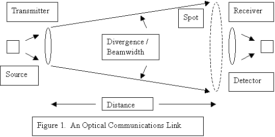
An optical communications link is sketched out in Figure 1.
The optical transmitter consists of a light source of some type, whose light output is modulated with our message information in some way, and then focused by some lens or mirror system. The source light is transported via some channel to the optical receiver. There the modulation is extracted and the message recovered.
In one simple system, the light source could be a flashlight, the modulation could be on-off keying in Morse code, the channel could be open air, the receiver could be a person’s eye … and we have a Boy Scout communication system across a lake.
It might be appropriate to say something about lenses and mirrors. If a source is spread out over such an aperture or a receiver is focused from such an aperture, the minimum beamwidth (divergence) from the aperture diameter D is about
divergence = wavelength of source / diameter of aperture (in radians)
That system can always be adjusted to NOT be that narrow a beam also. So for laser pointers that use 1 mm diameter of lens at 650 nm, we expect about 0.001 rad or 1 mrad of beam divergence … about 0.057 degrees … very narrow beam. That’s about what they do too. As might be expected, we have trouble aligning such a narrow beam, or actually keeping it that narrow as it spreads through real atmosphere with moisture droplets and with real scintillation and other temperature bending effects too.
The transmitter system tries to produce as great a power density as possible over a spot area at the receiver. Narrowing the transmitter beam and/or increasing the optical power increase the power density in that spot. The receiver is going to intercept a certain fraction of the transmitted power and recover the modulation on it.
With a gas laser or a laser diode module with focusing lens, it is not really very hard to produce a 1 mrad beam, so the need for additional mirror or lens focusing is usually unnecessary in the transmitter. Beamwidths less than a milliradian or so become very hard to aim and tend to “scintillate” on long paths, that is, “twinkle” as the very narrow beam is bent just slightly by the atmosphere and misses the receiver. The usual optical power produced by these CW lasers is in the area of 1 to 10 mW. This is not eye-damaging power, even if it only over a 1 mm diameter spot. That’s why these surces are usually used just as they are. Power density is simply the power out divided by the spot area. An example would be a laser pointer at a few inches. If the laser pointer puts out 3 mW over a 2 mm lens, the output beam power density is
P = 3e-3 / 3 / 1e-3 / 1e-3 = 1000 Watts/square meter (about the sun power density)
Other light sources, such as LED’s, have inherent beamwidths of a few degrees not unlike bare laser diodes. They also produce higher optical power out, but spread over a larger area, such that the power density is not eye-damaging. If we desire more power to the receiver, but still don’t want dangerous power density, a higher power source can be used with a 1 mrad beam by spreading the source over a larger area, then partially focusing it to the desired beamwidth. For instance, a 1 watt source in a 5 degree beam can be allowed to spread to cover a lens of 36 mm diameter to yield an output beam power density of
P = 1 / 3 / 18e-3 / 18e-3 = 1000 Watts/square meter also. (same … like the sun)
If both our example systems are adjusted for a 1 mrad beam, then at 1 kilometer away, the power density of the first example is about 3 mW spread over a spot about 1 sq m in area or P = 3e-3 Watts/sq m. In the second example, 1 watt is spread over that 1 sq m spot, so P = 1 Watt/sq m … a lot higher power density … 300 times or 25 dB higher.
Note that in both our examples, the beam power density is about the same as bright sun produces. You wouldn’t stare at the sun … so don’t stare into a laser or focused LED either. Besides … it’s BRIGHT … you’d want to turn away. This is a nice reason to experiment at visible wavelengths. If it looks bright, it IS bright. Turn your eyes away. That is a problem at near-IR. It’s invisible. A bright source can still damage your eyes, but it won’t clue you to turn away.
The object of the receiving system is to gather as much light as possible and focus it on the photodetector (PD) being used. To this end we would try to make the receiving optics have as large a capture area as possible. But increasing the receiver area does little good if that light is not focused on a photodetector, so that we have a bit of a geometrical relationship between the receiving lens or mirror and the size and beamwidth of the photodetector.
Many photodetectors are photodiodes and are flat and have an active area of about 1 mm x 1 mm. If we use such a photodetector with a laser pointer at 1 km producing a 1 m x 1 m spot, you can see that we intercept about 1 millionth of the source power. It’s simply the ratio of the area of the transmitter spot to the area of the receiver. So…
Pt = 3e-3 W and Pr = 3 e-9 W or S = -55 dBm at the receiver
With a photodiode detector, this is a nice strong signal for voice communication (a few kHz bandwidth). The field of view of the receiver is very wide, at least +- 45 degrees or 90 degrees total. This is the case for any flat unmagnified PD.
If we want to receive more signal, we have to increase the receiver capture area. Say we used a small 36 mm diameter lens as the receiver objective. The area of that lens is about 1000 sq mm … about 1000 times bigger than the bare photodetector … or 30 dB more light to the photodetector. But we have to make sure all that light is focused onto the 1 mm x 1 mm PD. This can be accomplished by using a convex converging lens and putting the PD at its focus. But then what is the field of view of this receiver system? Well, if the focused spot from the lens moves off the PD, the received signal drops a lot. The focused spot moves off the lens axis at the angle between the source and the lens axis, so we need to know the focal length of the lens and the size of the PD. For a 1 mm wide PD and a 100 mm focal length lens, we see that the source can be about +- 5 mrad off-axis to the lens. The field of view (FOV) of the receiving system is about 10 mrad. As you can see, the aiming of the receiver in this example is much less critical.
… more to come … de KB9II.